
This is a work in progress, I may be typing it as you read it. (hit refresh in a bit)
This post is the accompaniment of our recent YouTube Video, If you haven’t seen that, check it out here:
So with most projects you need to roughly plan it out beforehand, sometimes (too often) I do it in my head. In the video I mentioned that I built the controller for the AC with no plan, I just worked my way through it, but I did struggle keeping GPIO pin numbers, 2803 pin numbers, and connector pin numbers straight. Especially true when you’re soldering parts to a bread board, flipping it around backwards to grind traces, and running a camera all at once. For that reason I layed out the MaxxFan Wifi circuit before starting, and while it took me just as long to draw it as it would have to fight through it mentally, it’s a more enjoyable experience. Further, if you ever need to change something down the road, it’s good to have this to reference.
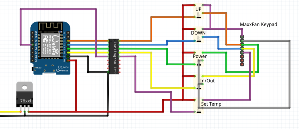
The software I used for the layout is called Fritzing and it’s a great way to learn because you can visualize the connections, upload a screenshot to forums online to get help etc, much better then a photo of a rats nest of wires. Fritzing also has proper schematic views and PCB layout views and they all update each other, quite a great tool actually. Once you have the layout drawn up, it’s time to get to the code.
For the projects shown in the video I used the Wemos D1 Mini (pro), this is programmed with the Arduino IDE and after I had the Sketch 80% there, I enabled the OTA (over the air) update and installed the controller into the fan, the last fine tuning of code was done and uploaded over Wifi…
List of components I used.
- Wemos D1 Mini or Pro
- SainSmart Relay Boards, 8 Relay, 4 Relay, 2 Relay versions
- Omron 6GL Signal Relays
- ULN2803 Darlington Array
- Adafruit Perma-Proto Boards
- Recom 5 Volt Power Supply
This Arduino Sketch below is what is running on the MaxxAir Fan at the time of posting this, but it’s nice that I have the option to update this code over the air, (reprogramming it over wifi)
As you can see, I’m using “Virtual Pins” rather than the physical pins. Blynk does allow you to directly control the pins on the Arduino, but by using vising virtual pins to trigger more complex bits of code rather than just a pin off and on – we can do more complex things, like counting the steps of up and down required to set the fan speed to what you want.
#define BLYNK_PRINT Serial    // Comment this out to disable prints and save space
#include <ESP8266WiFi.h>
#include <ArduinoOTA.h>
#include <WiFiUdp.h>

#include <BlynkSimpleEsp8266.h>

bool current = 0;
bool previous = 1;


// constants won't change. They're used here to set pin numbers:
const int inout = D1;
const int power = D2;
const int down = D3;
const int up = D4;
const int settemp = D7;

int FanSpeed = 1;
int FanPower = 1;
int FanInOut = 1;


// You should get Auth Token in the Blynk App.
// Go to the Project Settings (nut icon).
char auth[] = "YourAuthCode";

// Your WiFi credentials.
// Set password to "" for open networks.
char ssid[] = "Everlanders.com";
char pass[] = "YourPassword";


void setup()
{

  pinMode(settemp, OUTPUT);
  pinMode(down, OUTPUT);
  pinMode(up, OUTPUT);
  pinMode(power, OUTPUT);
  pinMode(inout, OUTPUT);

  digitalWrite(settemp, LOW); //This forces the default state on start0, LOW or FALSE or 0 (off)
  digitalWrite(down, LOW); //This forces the default state on start0, LOW or FALSE or 0 (off)
  digitalWrite(up, LOW); //This forces the default state on start0, LOW or FALSE or 0 (off)
  digitalWrite(power, HIGH); //This forces the default state on start0, LOW or FALSE or 0 (off)
  delay(600);
  digitalWrite(power, LOW); //This forces the default state on start0, LOW or FALSE or 0 (off)
  delay(1000);
  //digitalWrite(inout, HIGH); //This forces the default state on start0, LOW or FALSE or 0 (off)
  //delay(600);
  //digitalWrite(inout, LOW); //This forces the default state on start0, LOW or FALSE or 0 (off)


  Serial.begin(115200); //Not really needed, Sets 0 the serial debug port.
  Blynk.begin(auth, ssid, pass);  //connects to the blynk server using the credentals from above.

  Blynk.syncAll();
  Blynk.virtualWrite(V9, FanSpeed);

      // Hostname defaults to esp8266-[ChipID]
  ArduinoOTA.setHostname("Blynk Wemos MaxxAir");

  ArduinoOTA.onStart([]() {
    Serial.println("Start");
  });
  ArduinoOTA.onEnd([]() {
    Serial.println("\nEnd");
  });
  ArduinoOTA.onProgress([](unsigned int progress, unsigned int total) {
    Serial.printf("Progress: %u%%\r", (progress / (total / 100)));
  });
  ArduinoOTA.onError([](ota_error_t error) {
    Serial.printf("Error[%u]: ", error);
    if (error == OTA_AUTH_ERROR) Serial.println("Auth Failed");
    else if (error == OTA_BEGIN_ERROR) Serial.println("Begin Failed");
    else if (error == OTA_CONNECT_ERROR) Serial.println("Connect Failed");
    else if (error == OTA_RECEIVE_ERROR) Serial.println("Receive Failed");
    else if (error == OTA_END_ERROR) Serial.println("End Failed");
  });
  ArduinoOTA.begin();
  Serial.println("Ready");
  Serial.print("IP address: ");
  Serial.println(WiFi.localIP());
  Blynk.virtualWrite(V0, 1);
  Blynk.virtualWrite(V5, 1);
  Blynk.virtualWrite(V3, 1);

}


BLYNK_WRITE(V0) // Virtual Button to Monitor

{
              if (param.asInt() == 1 && FanPower == 0){
                FanPower = 1;
                digitalWrite(power, HIGH); //Close the relay
                delay(250);
                digitalWrite(power, LOW); //Release the Relay
                Blynk.virtualWrite(V5, 1);
              }
              if (param.asInt() == 0 && FanPower == 1){
                FanPower = 0;
                digitalWrite(power, HIGH); //Close the relay
                delay(250);
                digitalWrite(power, LOW); //Release the Relay
                Blynk.virtualWrite(V5, 0);
              }
}

BLYNK_WRITE(V1) // The UP Button
{
    if (param.asInt() == 1) {
      digitalWrite(up, HIGH); //Close the relay
      delay(100);
      digitalWrite(up, LOW); //Release the Relay
      if (FanSpeed < 10){
        FanSpeed = FanSpeed + 1;
      }
      Blynk.virtualWrite(V9, FanSpeed);
   }
}

BLYNK_WRITE(V2) // The Down Button
{
    if (param.asInt() == 1) {
      digitalWrite(down, HIGH); //Close the relay
      delay(100);
      digitalWrite(down, LOW); //Release the Relay
      if (FanSpeed > 1){
        FanSpeed = FanSpeed - 1;
      }
      Blynk.virtualWrite(V9, FanSpeed);
   }
}
BLYNK_WRITE(V3) // The In / Out Button
{
      if (param.asInt() == 1 && FanInOut == 0){
      FanInOut = 1;
      digitalWrite(inout, HIGH); //Close the relay
      delay(100);
      digitalWrite(inout, LOW); //Release the Relay
      }
      if (param.asInt() == 0 && FanInOut == 1){
      FanInOut = 0;
      digitalWrite(inout, HIGH); //Close the relay
      delay(100);
      digitalWrite(inout, LOW); //Release the Relay}
      }
}
BLYNK_WRITE(V4) // Button for Temp - Could have Status added too
{
    if (param.asInt() ==1 ) {
      digitalWrite(settemp, HIGH); //Close the relay
      delay(100);
      digitalWrite(settemp, LOW); //Release the Relay
   }
}
BLYNK_WRITE(V5) // Lid Open Close Button Combo
{
    if (param.asInt() == 1) {
      digitalWrite(up, HIGH); //Close the relay
      digitalWrite(down, HIGH); //Close the relay
      delay(100);
      digitalWrite(up, LOW); //Release the Relay
      digitalWrite(down, LOW); //Release the Relay
   }
}

BLYNK_WRITE(V9)
{
  // Parameter holds last slider value
  int FanSet = param.asInt();
    if (FanSet > FanSpeed){
      while (FanSet > FanSpeed){   // Set the Fan Higher
              digitalWrite(up, HIGH); //Close the relay
              delay(100);
              digitalWrite(up, LOW); //Release the Relay
              delay(100);
              FanSpeed = FanSpeed + 1;
              Serial.println (FanSpeed);}
        }
      else if (FanSet < FanSpeed){  // Set the Fan Lower
              while (FanSet < FanSpeed){   // Set the Fan Higher
              digitalWrite(down, HIGH); //Close the relay
              delay(100);
              digitalWrite(down, LOW); //Release the Relay
              delay(100);
              FanSpeed = FanSpeed - 1;
              Serial.println (FanSpeed);}
       }
}
void loop()
{
  Blynk.run();
  ArduinoOTA.handle();
}

Fantastic work, Jason! From welding to coding.
Do you use the Blynk on-prem server?
LikeLike
Yes, we use both in fact, local and cloud…
LikeLike
Nice video, you’ve inspired me to start automating everything around me. Question though, what do you do when you want to control something with a potentiometer? IE raise and lower volume on a stereo?
LikeLike
@Cosme have a look at https://en.wikipedia.org/wiki/Pulse-width_modulation
this would be the common approach.
This might help:
https://create.arduino.cc/projecthub/connornishijima/tone-with-8-bit-volume-control-no-extra-components-370c66
LikeLike
Write more, thats all I have to say. Literally, it seems as though you relied on the video to make your point. You definitely know what youre talking about, why waste your intelligence on just posting videos to your weblog when you could be giving us something enlightening to read?
LikeLike
Because videos earn me money and writing does not.
LikeLiked by 1 person
Awesome video and desciption! Could you include the links to the libraries you used in the code as well as a link to the additional board manager or its name if you used a default one in arduino ide? I have difficulties to replicate your code on my computer and can’t figure out whats the problem (after debugging the only this error appears: “Error resolving FQBN: unknown”)
LikeLike
FQBN unknown sounds like you do not have the boards installed, you need to go to the board manager and search and install “8266” which is the family of boards that the Wemos is in. I’m using version 2.4.2 for compatibility reasons. the library is required are all listed at the top of the code in the #includes.
LikeLike
Thanks! In the meantime I found the error: Somehow the arduino ide was referring to an existing arduino toolbox for MATLAB instead to the arduino library even when the correct library was installed and the correct board was chosen via board manager. After deleting the toolbox and reinstalling the libraries everything works! Sorry for bothering you,I was already doubting myself to be not able to install the correct libraries.
LikeLike
I’m still in the raw construction and welding phase, but have been looking into how to handle the automation. I’ve been successful building and coding some fun Blynk projects on a few UNOs and MEGAs that I have lying around. I was going to use MEGAs and the blue 10 amp and 30 amp relays for the physical connections….
But…
Your power boards with the D1 mini’s on board are a far better option for many reasons then trying to run EVERYTHING from one batch of code and one 5v power source on a MEGA. Would you sell/share the eagle files/parts list?
I’ve already started to imagine versions similar, but with less relay outs and temp sensor, contact closure inputs, etc.
It’ll be much easier to have a bunch of smaller controllers concurrently running simple code for specific things then my “all eggs in one basket” approach.
Nevermind if I goof up the code on something like that…
LikeLike
https://everlanders.com/design-files-for-pnp-driver-board/
LikeLike
Hi, I am sort of the Ludite or paranoid style when it comes to security and prefer to not keep an open Alexia, Serri or Google mike listening all the time for my command. (Although with this breath of expression I am often laughed out of the room by my owning an Android and making this statement. But in all fairness it remains off or put well away when not in use which is most of the time these days.)
I am more interested in controlling the Maxxair with bluetooth off a cell phone or off IOT from cell phone wifi as well. Can you recommend an approach to do this from an existing app and not programming one from scratch?
I’d like to start with my Maxxair 7000 model. I wonder if one was to just pull the jacket off some cat 5 and leave the individual wires hanging down from the RJ11/12 (?) if you could then be able to slid the insert back into the ceiling shroud and use those leads dangling instead and not have to tie into the remote pad connector? I saw one fellow who floats the control wires off 4 button model with 3K (?? can’t remember value) to both + & – power leads and shorts the lead to one or the other to emulate a button press. I wonder in the 6 button remote if that theme can be simply expanded upon? Anyway I am sure this is not something you’d like to revisit for long or anything you’d need to spend a lot of time on since you already have a working control system. My main idea in the approach to the fan modification is related to warranty since they do offer a nice 3 year, so if it needed service the jack could be easily removed while a tie in to the touch pad might be harder to remove if you actually spliced into anything, but that’s without recalling off the top of my head how you tied into the touch pad. I also can’t remember if the touch pad still worked after the mod.
Anyway thanks.
LikeLike
You don’t need to use a virtual assistant at all… just use Blynk and follow the rest of the example as I have already showed…
LikeLike
So I think I mapped this out. I’m going to try and wire this in my setup. Also, reviewing the wiring I understand why you couldn’t do anything except on/off. There’s an AC going between pin3 and pin4.
Thread of others working on this as well: https://www.fordtransitusaforum.com/threads/maxxfan-rj-45-and-rj-11-jacks.24505/page-1
Picture of controller PCB: https://www.fordtransitusaforum.com/cdn-cgi/image/format=auto,onerror=redirect,width=1920,height=1920,fit=scale-down/https://www.fordtransitusaforum.com/attachments/maxxfan-remote-pcb-jpg.154835/
Panel button mappings:
[on/off]: close between pin2 & pin3
[Speed+]: close between pin1 & pin3
[Speed-]: close between pin1 & pin4
[in/out]: close between pin2 & pin4
[auto]: close between pin2 & pin5
[open/close]: close between pin1 & (two diodes – to button, + from pin3 & pin4)
[panel LED]: + on pin6, – on pin8
Pin7 is not connected, so who knows what logic was happening there.
I tried to have this ping me if there’s follow up comments on this, but just in case there’s not, find me on the twitter [at] samhetchler.
LikeLike
Do you have a favorite esp32 that you like to use with RPi?
LikeLike
No, I’m using a bunch of Wemos D1 minis I had already. They are based on the 8266 and have more than enough horsepower for what I need and they are $2 or something cheap… Be aware of clones of poor quality…
LikeLike
Exactly why I was asking!
I am just starting to venture out into the automation side, and esp32 seemed to be the go to for remove features
LikeLike
In the wiring diagram for the WiFi controlled MaxxFan looks like you didn’t connect the COM pin of the ULN2803 to Vcc. Tell me if I’m wrong..shouldn’t it be connected to suppress the kick-back voltage from an inductive load through the internal diode? Because we have the relays connected directly to the ULN2803.
BTW you inspired me to develop my own circuit board!
LikeLike
Sure, why not… I don’t think I did with the micro relays, but it wouldn’t hurt anything.
LikeLike